TEST METHOD OF MARSHALL STABILITY AND FLOW OF BITUMINOUS MIXTURE USING MARSHALL APPARATUS
TEST STANDARD: AASHTO: T245-94
OBJECTIVE: To determine the measurement of the resistance to plastic flow of cylindrical specimens of bituminous mixture loaded on the lateral surface by means of the marshall apparatus. This method is applicable with mixtures containing asphalt cement, asphalt cutback or tar and aggregates upto maximum 25.4mm size.
APPARATUS:
Cylindrical mould: Diameter 101.4mm and height 76.2mm with base plate and extension collar.
Specimen extractor: Steel, in the form of a disk with a diameter not less than 100mm and 12.7mm thick for extracting the compacted specimen from the compacted mould with the use of extension collar while extracting the specimen.
Compaction hammer: The compaction hammer shall have a flat, circular tamping face and 4536 ± 9 gms sliding weight with a free fall of 457.2 ± 1.524mm
Compaction pedestal: The compaction pedestal shall consists of an 203.2 by 203.3 by 457.2mm wooden post capped with a 304.8 by 304.8 by 25.4mm steel plate. The wooden post shall ne oak, pine or any other wood having an average dry density of 0.67 to 0.77 gm/cc. The wooden post shall be secured by four angle brackets to a solid concrete slab. The steel cap shall be firmly fastened to the post. The pedestal assembly shall be installed so as the post is plumb and the cap is level.
Specimen mould holder: It is mounted on the compaction pedestal so as to counter the compaction mould over the centre of the post. It shall hold the compaction mould, collar and base plate securely in position during compaction of the specimen.
Breaking head assembly: The breaking head shall consists of upper and lower cylindrical segments or test heads having an inside radius of curvature of 50.8mm accurately machined. The lower segment shall be mounted on a base having two perpendicular guide rods or post extending upward. Guide sleeve in the upper segment shall be in such a position as to direct the two segments together without appreciable binding or loose motion on the guide rods.
Breaking head assembly: The breaking head shall consists of upper and lower cylindrical segments or test heads having an inside radius of curvature of 50.8mm accurately machined. The lower segment shall be mounted on a base having two perpendicular guide rods or post extending upward. Guide sleeve in the upper segment shall be in such a position as to direct the two segments together without appreciable binding or loose motion on the guide rods.
Loading jack: The loading jack shall consists of a screw jack mounted in a testing frame and shall have uniform vertical movement of 50.8mm/minute. An electric motor may be attached to the jacking mechanism.
Proving ring: It shall be of minimum capacity of 22.2KN fitted with a dial gauge of graduated in minimum 0.0025mm.
Dial Gauge: It shall be capacity of maximum 5mm with least count of 0.01mm
Other apparatus: Hot air oven, hot plate or heating device, Mixing apparatus, Constant Temperature water bath, containers for heating aggregates and bitumen, thermometers, mixing tools, weighing balance of 2Kg with sensitive of 0.1gms, 5Kg sensitive to 1gms, hand gloves, scoop and spoons.
PROCEDURE FOR STABILITY AND FLOW TEST
Prepare at least three specimens for each combination of aggregate and bitumen content. Dry aggregates to constant mass at 105-110oC and separate the aggregates by dry sieving into the desired size fractions with following sizes:
25mm to 19mm, 19mm to 9.5mm, 9.5mm to 4.75mm, 4.75mm to 2.36mm, Passing 2.36mm
Mixing temperature and compacting temperature:
Asphalt Cement: The temperature to which the asphalt cement must be heated to produce a viscosity of 170±20 cst shall be mixing temperature and temperature to produce a viscosity of 280±30 cst shall be compacting temperature.
Asphalt cut back: The temperature to which the asphalt cement must be heated to produce a viscosity of 170±20 cst shall be mixing temperature and temperature to produce a viscosity of 280±30 cst shall be compacting temperature.
Tar: The temperature to which the tar must be heated to produce a Engler specific viscosities of 25±3 and 40±5 shall be respectively the mixing and compacting temperature.
An initial batch shall be mixed for the purpose of buttering the mixture bowl and stirrers. This batch shall be emptied after mixing and the sides of the bowl and stirrers shall be cleaned off mixture residue by scraping with small spatula but shall not be wiped with cloth or washed clean with solvent except when a change is to be made in the binder.
Weight in separate pan for each test specimen the amount of each of the size fraction required to produce a batch that will result in a compacted specimen 63.5±1.27mm in height, total weight of all materials shall be about 1200 gms for casting single test specimen. Mix the aggregate in each pan and place the pans in hot air oven and heat to a temperature as specified above by more than 280C for asphalt mixes and tar mixes and 140C for cutback asphalt mixes. Heat to the stabilised

temperature just sufficient bituminous material for the batch in a separate container. Charge the mixing bowl with the heated aggregate. Form a crater in the dry blended aggregate and weigh the preheated required amount of bituminous material into the mixture. For mixes prepared with cutback asphalt, introduce the mixing blade in the mixing bowl and determine the total mass of the mix components plus bowl and blade before proceeding with mixing. Care must be exercised to prevent loss of material during mixing and subsequent handling. At this point the temperature of the aggregates and bitumen shall be within the mixing temperature as specified above. Mix the aggregate and bituminous material rapidly until thoroughly coated.
Following mixing, cure asphalt cutback mixtures in a ventilated oven maintained at approximately 11.10C above the compaction temperature. Curing is to be continued in the mixing until pre-calculated weight of 50% solvent loss or more has been maintained. The mix shall be stirred in a mixing bowl during curing to accelerate the solvent loss. However care shall be exercised to prevent the loss of mix. Weight the mix during curing in successive intervals of 15 minutes initially and less than 10 minute intervals as weight of the mix at 50% solvent loss is approached.
Thoroughly clean the specimen mould assembly and the face of the compaction rammer and heat them to a temperature in between 930C to 148.90C. Place piece of filter paper cut to size in the bottom of the mould before the mixture is introduced. Place the entire batch in the mould. Spade the mixture vigorously with heated spatula or trowel 15 times around the perimeter and 10 times over the interior. Remove the collar and smooth the surface of the mix with a trowel to a slight rounded shape. Replace the collar, then place a filter paper cut to size on top of the mould assembly on the compaction pedestal in the mould holder, and apply 75 blows with a compaction rammer with a freefall of 457.2mm. Hold the axis of the compaction hammer perpendicular to the base of the mould assembly during compaction. Remove the base plate and collar, reverse and reassemble the mould. Apply the same number of blows to the face of the reversed specimen. Place the mould with specimen in air and allow it to cool until sufficient cohesion has been developed to result in the proper cylindrical shape of the compacted specimen, generally for a period of 24 hours. After cooling, extract the specimen from the mould by placing a steel plate on top of the specimen and apply the load using load transfer bar by placing a steel ball in between plate and load transfer bar. Strike on top of the load transfer bar with hammer repeatedly until the specimen is completely extracted from the mould.
Bring the specimens prepared with asphalt cement and tar to the specified temperature by immersing in the water bath for a period of 30 to 40 minutes, water bath being maintained at a temperature of 60±10C for asphalt cement and 37.8±10C for tar specimens. Bring the specimens prepared with asphalt cutback to specified temperature by placing in an air bath for a minimum

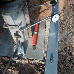
period of 2 hours, air bath being maintained at 25±10C. Thoroughly clean the guide rods and the inside surfaces of the test heads prior to making the test and lubricate the guide rods so that the upper test head slides freely over them. The testing temperature shall be maintained between 21.2 to 37.80C using water bath when required. Place the specimen in the lower segment of the breaking head, place the upper segment of the breaking head over the specimen and place the complete assembly in position on the testing machine. Assemble the dial gauge in position over one of the guide rods and adjust the dial gauge to zero while holding the sleeve firmly against the upper segment of the breaking head while the test load is being applied. Apply the load at a constant rate of 50.4mm per minute until the maximum load is reached and record the maximum load in proving ring and maximum deformation in the dial gauge. Proving ring reading gives the value of stability and dial gauge reading provides the value of flow. If the height of the specimen is less than or greater than 63.5mm, then correction factor shall be applied to the measured value of stability as per below table:
Corrected stability = Measured stability x Correction factor
| S No | Volume of specimen ( cc) | Thickness of specimen (mm) | Correction factor |
| 1 | 200 to 213 | 25.4 | 5.56 |
| 2 | 214 to 225 | 27.0 | 5.00 |
| 3 | 226 to 237 | 28.6 | 4.55 |
| 4 | 238 to 250 | 30.2 | 4.17 |
| 5 | 251 to 264 | 31.8 | 3.85 |
| 6 | 265 to 276 | 33.3 | 3.57 |
| 7 | 277 to 289 | 34.9 | 3.33 |
| 8 | 290 to 301 | 36.5 | 3.03 |
| 9 | 302 to 316 | 38.1 | 2.78 |
| 10 | 317 to 328 | 39.7 | 2.50 |
| 11 | 329 to 340 | 41.3 | 2.27 |
| 12 | 341 to 353 | 42.9 | 2.08 |
| 13 | 354 to 367 | 44.4 | 1.92 |
| 14 | 368 to 379 | 46.0 | 1.79 |
| 15 | 380 to 392 | 47.6 | 1.67 |
| 16 | 393 to 405 | 49.2 | 1.56 |
| 17 | 406 to 420 | 50.8 | 1.47 |
| 18 | 421 to 431 | 52.4 | 1.39 |
| 19 | 432 to 443 | 54.0 | 1.32 |
| 20 | 444 to 456 | 55.6 | 1.25 |
| 21 | 457 to 470 | 57.2 | 1.19 |
| 22 | 471 to 482 | 58.7 | 1.14 |
| 23 | 483 to 495 | 60.3 | 1.09 |
| 24 | 496 to 508 | 61.9 | 1.04 |
| 25 | 509 to 522 | 63.5 | 1.00 |
| 26 | 523 to 535 | 65.1 | 0.96 |
| 27 | 536 to 546 | 66.7 | 0.93 |
| 28 | 547 to 559 | 68.3 | 0.89 |
| 29 | 560 to 573 | 69.9 | 0.86 |
| 30 | 574 to 585 | 71.4 | 0.83 |
| 31 | 586 to 598 | 73.0 | 0.81 |
| 32 | 599 to 610 | 74.6 | 0.78 |
| 33 | 611 to 625 | 76.2 | 0.76 |
Read more :
- Penetration Value of Bitumen
- Method of Softening point test of bitumen
- Determination of stripping value of Road aggregates
- Specific gravity of Bitumen

Founder & Admin of civilengineeringsolution.com, I am a civil engineer working as a Engineer (QA/QC).